Discover the capabilities of WaveMode AFM in characterizing bottlebrush polymers with unprecedented detail and speed, ...

15.09.2023
Héctor here, your AFM expert at Nanosurf calling out for people to share their Friday afternoon experiments. Today I bring you coding, automatization, scaling up of processes, 2D materials, and, of course, some fun.
In a past life I used to work on 2D materials, and it is a branch of research that still captures my imagination, because you can use proximity effects to tune properties like magnetism or electrical conduction. However, one of the main challenges is to scale up mass production of devices based on these materials. This is why when I saw this post I couldn't refrain my enthusiasm.

There I was, again embarked on another weird project. (By the way, here is the link to the Twitter post , and most interestly to the nice publication by Andrés and his group https://onlinelibrary.wiley.com/doi/10.1002/smtd.202300326)
Surely scanning while spinning was out of the question, not just the bumps on the tape and the eccentricity of the cylinder, but also the vibrations on the ball bearings... and the boredom of people, because stopping the rotation and scanning should be possible, just too boring for someone to sit there and take a hundred scans... unless it can be easily scripted and automatized.
So this is the perfect excuse to play with Nanosurf Python interface.

My quick idea to condense everything onto a Friday afternoon experiment is to quickly prototype the mechanical part with Lego (this allowed me to go through several iterations extremely quickly), use an Arduino and a servo to do the rotation, and use Python to control the Arduino and our AFM software so I can let the system run on its on collecting information.
So this is the contraption I came up with. Two wheels of different sizes to make sure it is not always the same area of the wheels in contact, a servo motor to move a defined amount, and an Arduino UNO board listening to the serial communication and telling the servo when to rotate.

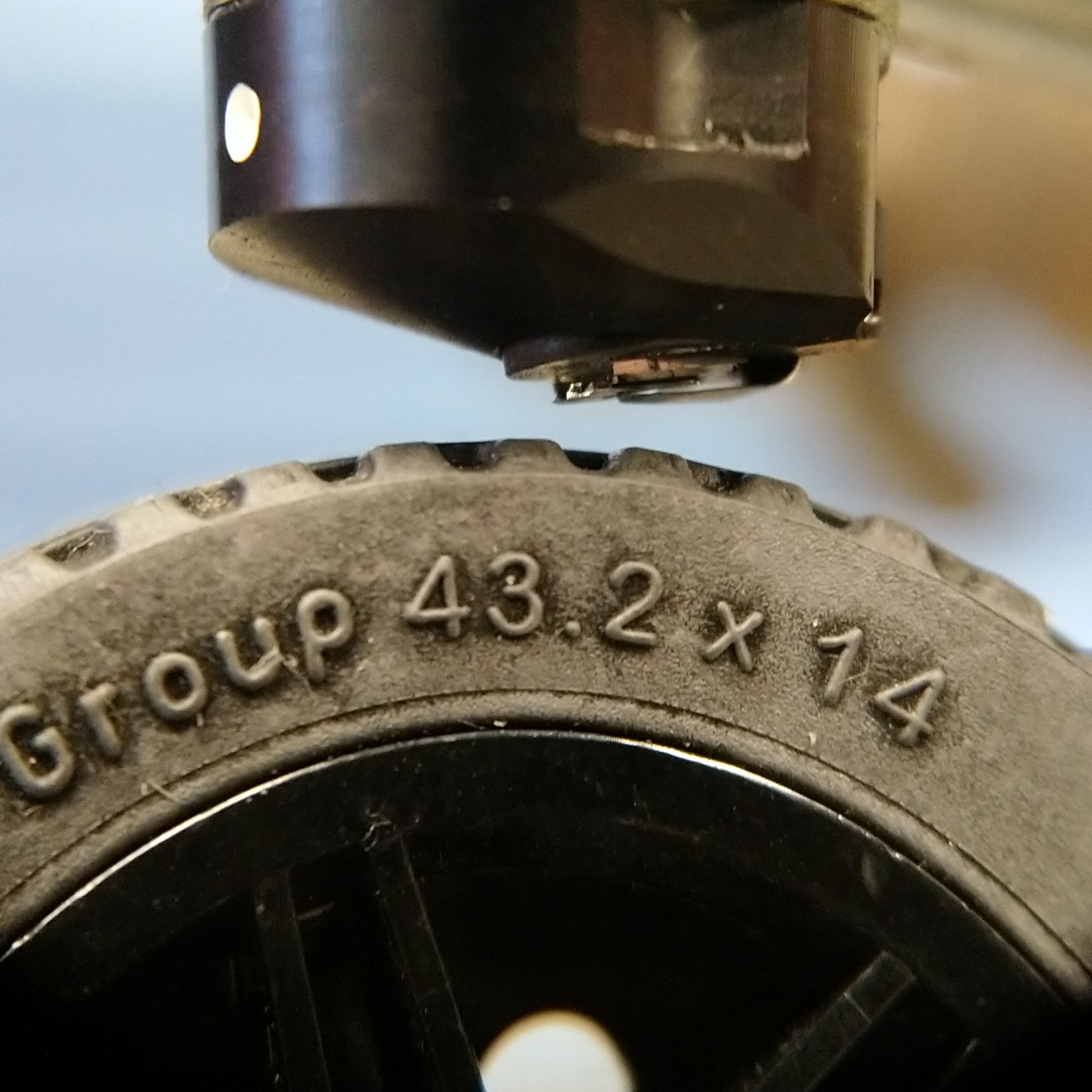
Not what you would call a polished product... but it seems to do the job. By the way, the MoS2 powder was relatively easy to acquire (got it off Amazon), the drawback is that the flake size is about 1.5 μm. The servo is from the PiHut shop of Arduino and Raspberry Pi products and is designed to be Lego compatible.
Next is the Arduino code. It simply waits to receive a command through the serial port and then rotates the servo back and forward (this is a 180 deg servo, so only moves 90 deg in each direction and doesn't allow multiple rotations, that's why this movement, but on the bright side of things, it has a position sensor).
Hopefully I added enough comments to understand the code. Note: It is very important the step where the control pin of the servo is initialize to zero, otherwise the servo will rotate on start-up, and that can be... let's say catastrophic for the AFM, if things start spinning when for instance power goes off and on again.
With the Arduino part ready, it is time for the Python, which is relatively straight forward checking the examples included with our Python library and the documentation. Basically, I want to run the AFM software, have the probe mounted, laser aligned and type of probe selected, and starting with the system fully retracted, I want the Python script to take over and land on the surface, capture an optical image of the surface, then scan a couple of times (things are going to be loosely attached), then fully retracting, tell the Arduino to rotate... and repeat the process.
The diagram is something like this:

The python code is quite simple. In principle, if one knows the scan parameters beforehand, they can be set manually and only use Python to approach, scan, retrac, rotate Arduino, but I want this to be as didactic as possible, so I included some set-up commands as a reference for those less familiar with them.
#%%#
Importing Libraries
import nanosurf
import serial
import time

#### Making some definitions
# First Nanosurf
spm=nanosurf.SPM()
application = spm.application
scan = application.Scan
application.AutoExit = False
opmode = application.OperatingMode
approach = application.Approach
zcontroller = application.ZController
Video=application.Video
# Second Arduino
arduino = serial.Serial(port='COM6', baudrate=9600, timeout=5)
def arduinowrite():
    #This writes to the Serial port the letter u.
    #It flush the input and output to prevent the communication
    #from clogging with data.
    #The waits are there to stop Python, otherwise can be a race
    #condition with Python trying to access the serial port and is still in use.
    time.sleep(1)
    arduino.flushInput()
    time.sleep(1)
    arduino.flushOutput()
    time.sleep(1)
    arduino.write(bytes(b"u"))
    time.sleep(1)

#### Setting scan parameters
scanrepetitions=3
scansize=10e-6
pixel=256
scantime=0.405
scan.ImageSize(scansize,scansize)
scan.Scantime=scantime
scan.Points=pixel
scan.Lines=pixel
scan.Rotation=15

#### Setting approach conditions
approach.ApproachSpeed=0.12 # 1 corresponds to 100%
approach.AFMApproachMode=0
approach.AutoStartImaging = False
opmode.OperatingMode=4 #Phase contrast imaging mode
opmode.VibratingAmpl = 2.3
zcontroller.SetPoint = 50 # Set the setpoint to 50%
zcontroller.PGain = 3000 # Set P-gain to 3100
zcontroller.IGain = 3500 # Set I-gain to 3500
zcontroller.DGain = 2300 # Set I-gain to 3500
application.LoadChartArrangement("superdupper_chart.chart") #Loads my preferred chart arrangement.

Video.VideoSource=0 #Chosing which camera is active to take an image of the optical view.

#%% Main loop
#Approaches, takes number of scan, then retracts to Home, then rotates the arduino, and repeats

time.sleep(20) #Most of these are here to either avoid race conditions,
#or to prevent overloading the processor with code running as fast as it can.

numofiterations = 0

while True:
    print("Rotation iteration # "+str(numofiterations))

    # Approach from home position (can take a while)
    approach.StartApproach()
    while approach.IsMoving == True:
        time.sleep(20)
        print("Approaching")

    # Change the AFM image savename to indicate how many rotations have been done.
    mask = "MoS2_"+str(numofiterations)+"-[INDEX]"
    time.sleep(5)
    application.SetGalleryHistoryFilenameMask(mask)
    time.sleep(5)

    #Saves a screenshot from the active optical view.
    Video.SaveFrameMPX2(r"C:\Users\corte\AppData\Local\Nanosurf\Nanosurf C3000\History\MoS2_"+str(numofiterations)+".JPG")
    time.sleep(5)

    # Start scan
    for k in range(scanrepetitions):
        scan.StartFrameUp()
        while scan.IsScanning == True:
            time.sleep(40)
            print("Currently scanning")

    # Slow widthraw
    approach.StartWithdraw()
    while approach.IsMoving == True:
        time.sleep(20)
        print("Retracting")

    # Fast widthraw to home position
    approach.StartHome()
    while approach.IsMoving == True:
        time.sleep(20)
        print("Retracting")
    time.sleep(10)
    application.PrintStatusMsg('biiii') #This is an easter egg.

    #Arduino code to perform 10 rotations
    for m in range(10):
        print("About to do the Arduino")
        arduinowrite() #Does one iteration of the back and forth movement.
        print("Arduino done")
        time.sleep(20)
        numofiterations =numofiterations+1
 The answer is yes, but I have to be honest, the AFM imaging is hard to do at the beginning when things are loose. So many of the images have poor surface tracking.
So, in summary, I managed to scan on top of the rolling mechanism (but not while rolling), and obtained images showing how the MoS2 flake coverage changes over time. This could be applied in-line during manufacturing processes, or as a part of research to determine the optimal conditions.
Message to take home: scripting can help automate AFM imaging, and opens new research avenues where the AFM captures lots of data unsupervised.
Hope you enjoyed what I showed you, and that it serves as a guide to do more fun and interesting stuff, please, stay in touch, and if you have more info or comments, please share with me.
28.10.2025
Discover the capabilities of WaveMode AFM in characterizing bottlebrush polymers with unprecedented detail and speed, ...

27.10.2025
Read this blog and discover advanced alloy engineering and cutting-edge AFM techniques for high-resolution, ...

14.10.2025
Discover how WaveMode technology resolves the tobacco mosaic virus structure under physiological conditions with ...

08.12.2024
Learn how to make a Python code to interface your AFM with a gamepad.
01.10.2024
Discover how different types of glass age and degrade over time, and learn how to use AFM technology to investigate ...
11.07.2024
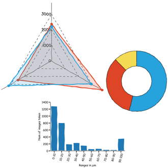
FridayAFM: learn how to perform datamining on large sets of AFM data.
Interested in learning more? If you have any questions, please reach out to us, and speak to an AFM expert.