Discover how Nanosurf's industrial automated AFM systems are developed from concept to delivery, ensuring precise ...

16.02.2024

Héctor here, your AFM expert at Nanosurf calling out for people to share their Friday afternoon experiments. Today I explore how to simulate cantilever artefacts using Unity.
There are several things that contribute to acquiring good AFM data: having the right sample and mounting it properly, using the right instrument and the right mode for the task, setting the instrument properly, analizing the data, knowing the sample, recognizing artefacts... and whilist I think it is impossible to atribute an order based on importance, I do think there is one topic that is not discussed enough. You guessed right, I'm talking about artefacts again.
In a previous post called Frankenstein's Monsters, I showed you the effect that tip damage can have on different samples and what types of artefacts they can generate. Moreover, I also included a tutorial of how to use Gwyddion to generate such artefacts so you will be able to recognize them when they appeared. However, I felt that that method was not complete because it only included the tip apex, and not the rest of the AFM probe. That is why I decide to code it by myself using Unity.
Why Unity? Well, you see, on a past life I did some game coding, and Unity is a versatile tool that takes care of the physics and rendering engine and lets you focus on the playability and story telling. In other words, with very little effort you can set up something that already simulates pretty well the physics of the real world.

What is even better, Unity lets me use the printable 3D AFM probe models I designed with an easy import of the geometry.

So, how the "game" I designed in Unity works?
1. Created an object called Probe which will host the main script and the geometrical parts of the probe (I had to split it so the resulting collision box for each part is at the same time convex and following the geometry).
2. The probe parts will have mesh colliders that will set flags indicating collision with another meshes.
3. The surface elements have all the same tag, and all of them have mesh
4. The Probe object has a rigid body, meaning that any collision flag of its child (the probe parts) will travel back to the Probe object.
5. The script attached to the Probe object will move the probe in x and z (y is the height), and at each location will start at a set y height and will reduce the height until a collision with the surface is triggered. When a collision is detected, the height is stored in a txt file.
6. The txt file created can be opened in Gwyddion as raw data file. I need to input manually the number of rows and columns.
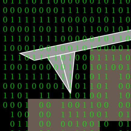
All together, something like this:
This is the C# script to move the probe and save the data.
using System.Collections;
using System.Collections.Generic;
using UnityEngine;
using System.IO;
public class AFM_probe : MonoBehaviour
{
    //Variables that are accesible from the Unity editor.
    public float xlenght= 10;
    public float xpixels= 10;
    public float zlenght= 10;
    public float zpixels= 10;
    public string save_name= "default";
    public float speed=0.03f;
    int mytimer=0;
    // Start is called before the first frame update
    void Start()
    {
        transform.position = new Vector3(-xlenght/2, 0.25f, -zlenght/2);
        // Start by placing the probe in the initial position
    }
    // Update is called once per frame
    void FixedUpdate()
    {
        //Forget the timer for now, the update part just moves the probe downat a constant speed.
        mytimer=mytimer+1;
        var x= this.transform.position.x;
        var y= this.transform.position.y;
        var z= this.transform.position.z;
        y=y-speed;
        transform.position=new Vector3(x,y, z);
    }
    //void OnCollisionEnter(Collision collision)
    void OnTriggerEnter (Collider a)
    {
        //A collision trigered by one of the child objects (tip, cantilever or chip) initializes this function.
        //The timer is because sometimes a triger is still active after been triggered, so we allow some time before allowing a collision to trigger this part of the script.
        if (mytimer>3)
        {
            mytimer=0;
            var z= this.transform.position.z;
            //If the z variable is larger than this value it means the scanning has finished.
            if(z<zlenght/2)
            {
                //Creates or writes to a txt file the value of y when the collision happened.
                string path = "Assets/Resources/"+save_name+".txt";
                StreamWriter writer = new StreamWriter(path, true);
                var y= this.transform.position.y;
                writer.WriteLine(y.ToString()+"; ");
                writer.Close();
                var x= this.transform.position.x;

                //Keeps moving along x unless the end of the line was reached, in which case it adds one step in z and starts scanning in x again
                if (x<xlenght/2)
                {
                    x=x+xlenght/xpixels;
                    transform.position = new Vector3(x, 0.25f, z);
                }
                else
                {
                    z=z+zlenght/zpixels;
                    transform.position = new Vector3(-xlenght/2, 0.25f, z);
                }
            }
            if (z>zlenght)
            {
                //This doesn't work in the editor to stop the application, but should work once compiled
                Application.Quit();
            }
        }
    }
}
Did it work?
As you can see, it does recreate the basic cantilever re-lated artefacts, such as shadows from large structures because the tip is imaging in air (the cantilever is touching). Missing details and widened structures. The self-image of the probe when imaging sharp objects, and in general, in tall structures, very different sides.
Let's recap. Image artefacts can occur due to many reasons, one of which is due to cantilever interaction with the sample. Hopefully today we managed to review the most basic ones, so if you ever encounter them, it will be easy to recognize them.
I hope you find this useful, entertaining, and try it yourselves. Please let me know if you use some of this, and as usual, if you have suggestions or requests, don't hesitate to contact me.
25.02.2026
Discover how Nanosurf's industrial automated AFM systems are developed from concept to delivery, ensuring precise ...

10.02.2026
High-end industrial solution are powered by accurate software that coordinate all their functions. Discover the ...

20.01.2026
Read how Nanosurf designs AFM stages to meet industrial challenges, ensuring precision and stability in AFM systems for ...

08.12.2024
Learn how to make a Python code to interface your AFM with a gamepad.
01.10.2024
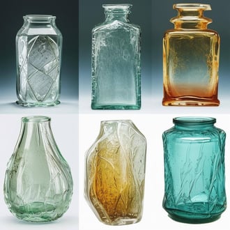
Discover how different types of glass age and degrade over time, and learn how to use AFM technology to investigate ...
11.07.2024
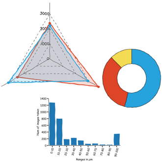
FridayAFM: learn how to perform datamining on large sets of AFM data.
Interested in learning more? If you have any questions, please reach out to us, and speak to an AFM expert.